Design
 Hardware
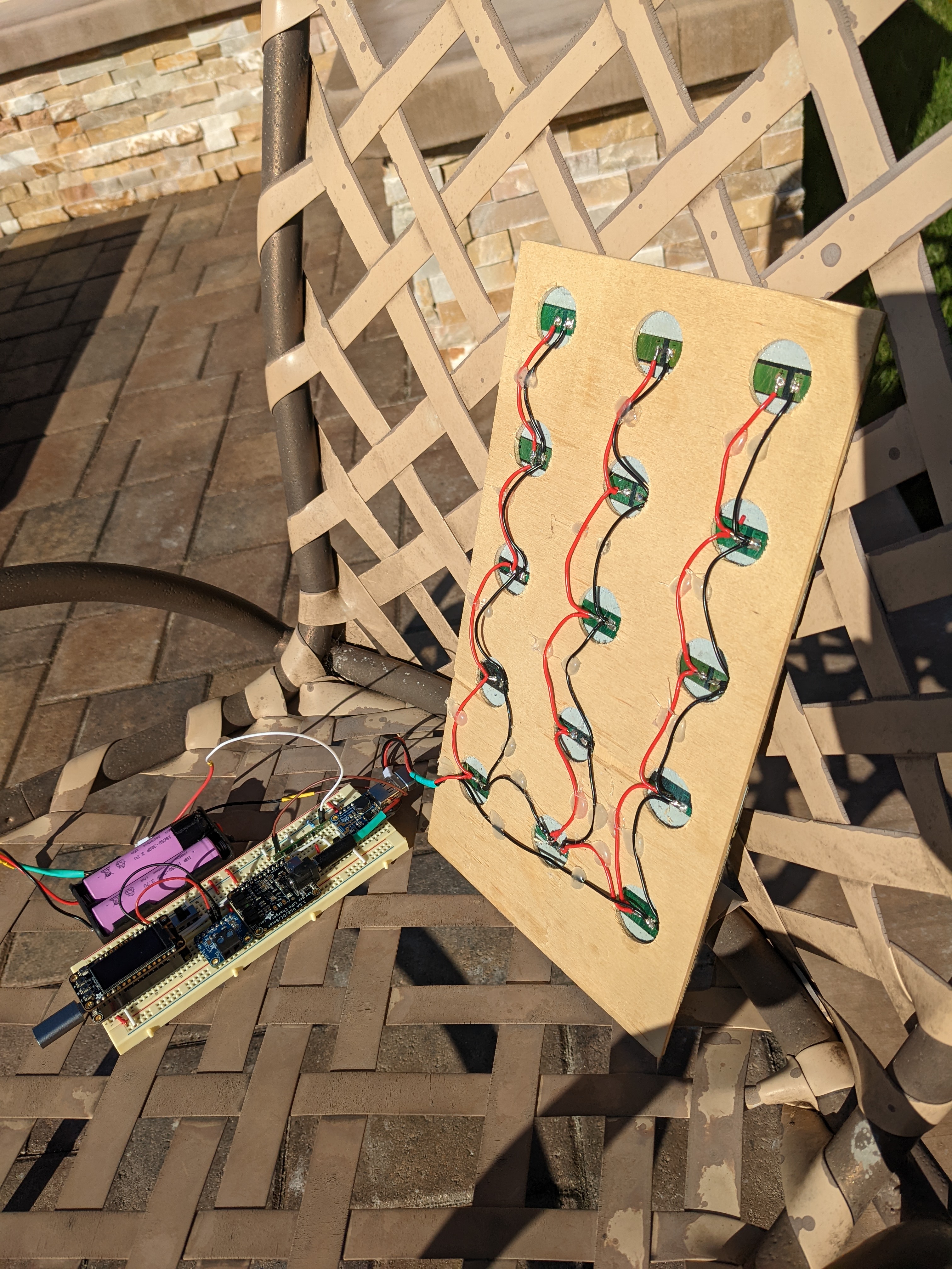
- 15X Energizer LED Solar pathway Lights
- 1X Adafruit Feather HUZZAH32 ESP32
- 1X Adafruit 128x64 OLED FeatherWing
- 1X Adafruit INA260 Current + Voltage + Power Sensor Breakout
- 1X Adafruit Universal USB / DC / Solar Lithium Ion/Polymer charger - bq24074
- 1X Adafruit PowerBoost 1000 Basic - 5V USB Boost
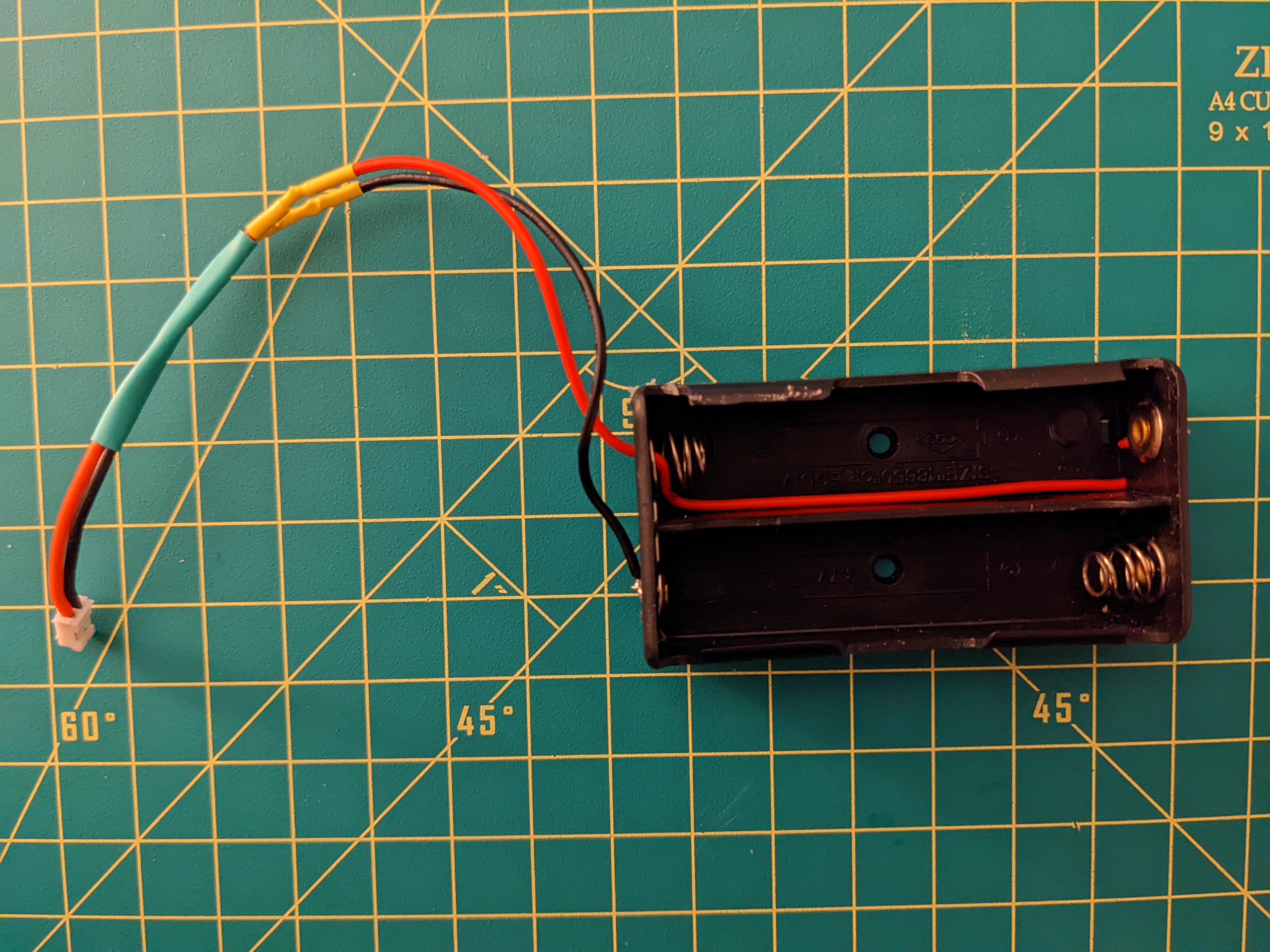
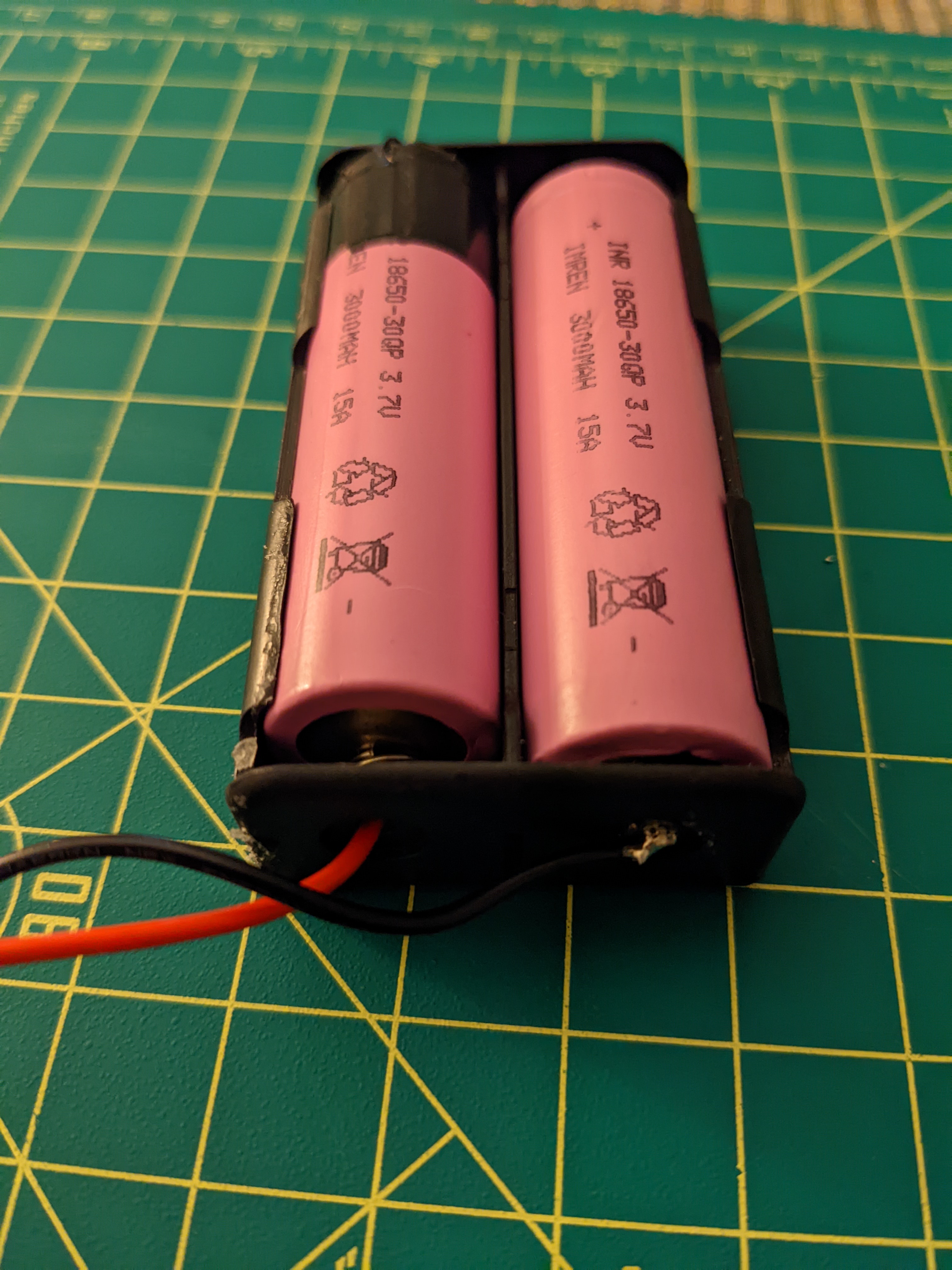
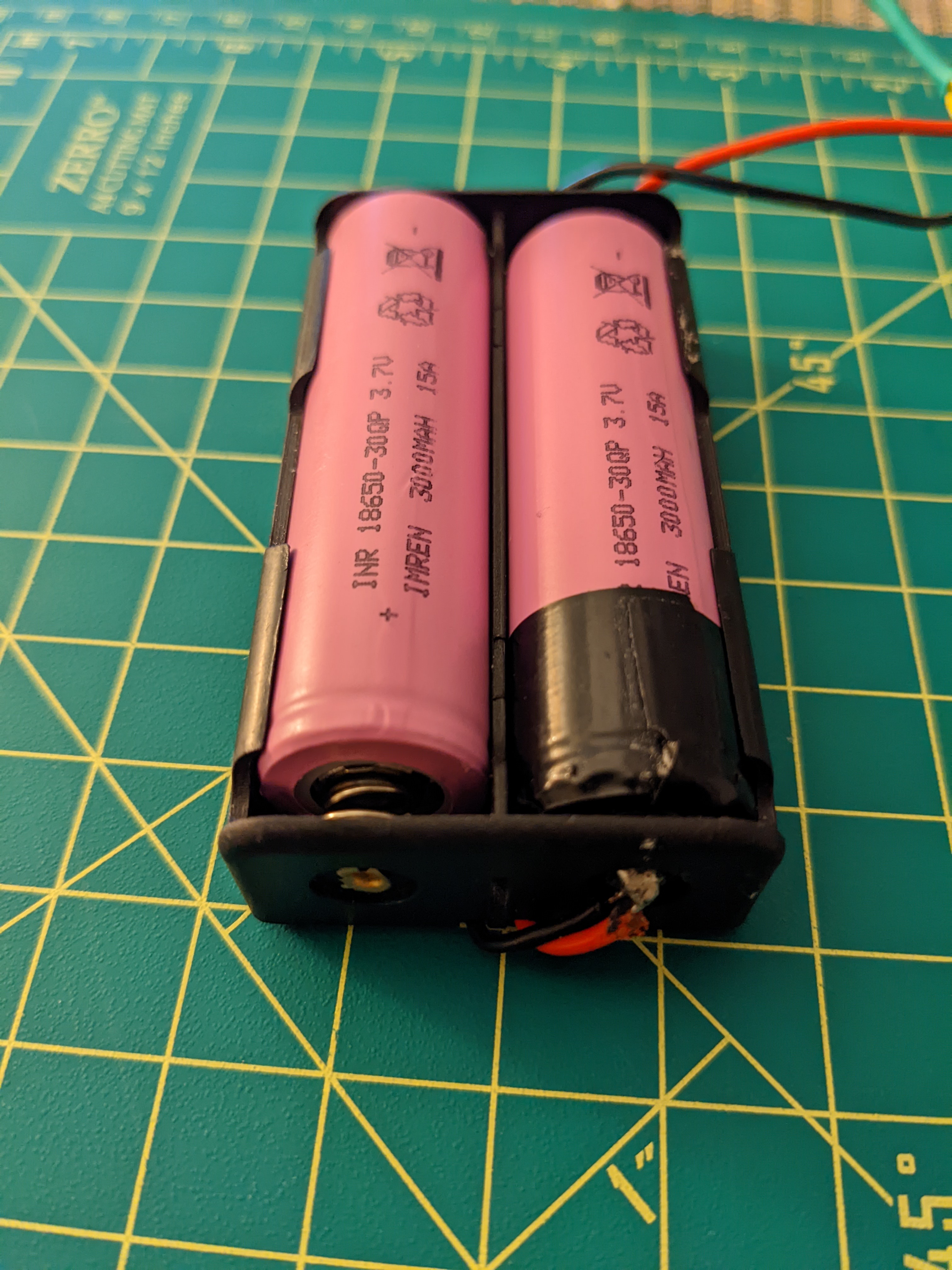
- 2X IMREN 3.7v 18650 Rechargeable Battery 3000mAh
- 1X NITECORE UMS2 Charger
- 1X 18650 2 Battery Holder 7.4V
- 1X EBL 9V Li-ion Battery Charger
- 1X CT-Energy Lithium Coin Button Batteries Charger
- 1X 10kΩ Resistor
- 1X Adafruit Feather Stacking Headers - 12-pin and 16-pin female headers
- 2X Cylewet 5mm High Knob Vertical Slide Switch 3 Pin 2 Position 1P2T SPDT Panel
- 1X ELEGOO 3pcs Breadboard 830 Point Solderless Prototype PCB Board Kit
- 1X Anmbest 5PCS 1S 3.7V 4A 18650 Charger PCB BMS Protection Board
Note
If the output from the battery turns off, it may be because the BMS needs to be reset. This may be done by shorting the P- and B- on the BMS.
I opted to drop support for the ESP8266 for a few reasons:
- The need to short pin
16in order to wake the Feather from deeps sleep removes the ability to use buttonBon the OLED screen. - Button
Aon the OLED screen was tied to the Feather LED. - There is no way to determine the method that was uesd to wake the Feather.
 Electronics
On the bq24074, carefully cut the 1.0A jumper and solder the 1.5A to increase the current limit. This needs to be verified that the panel is actually outputting more than 1A.
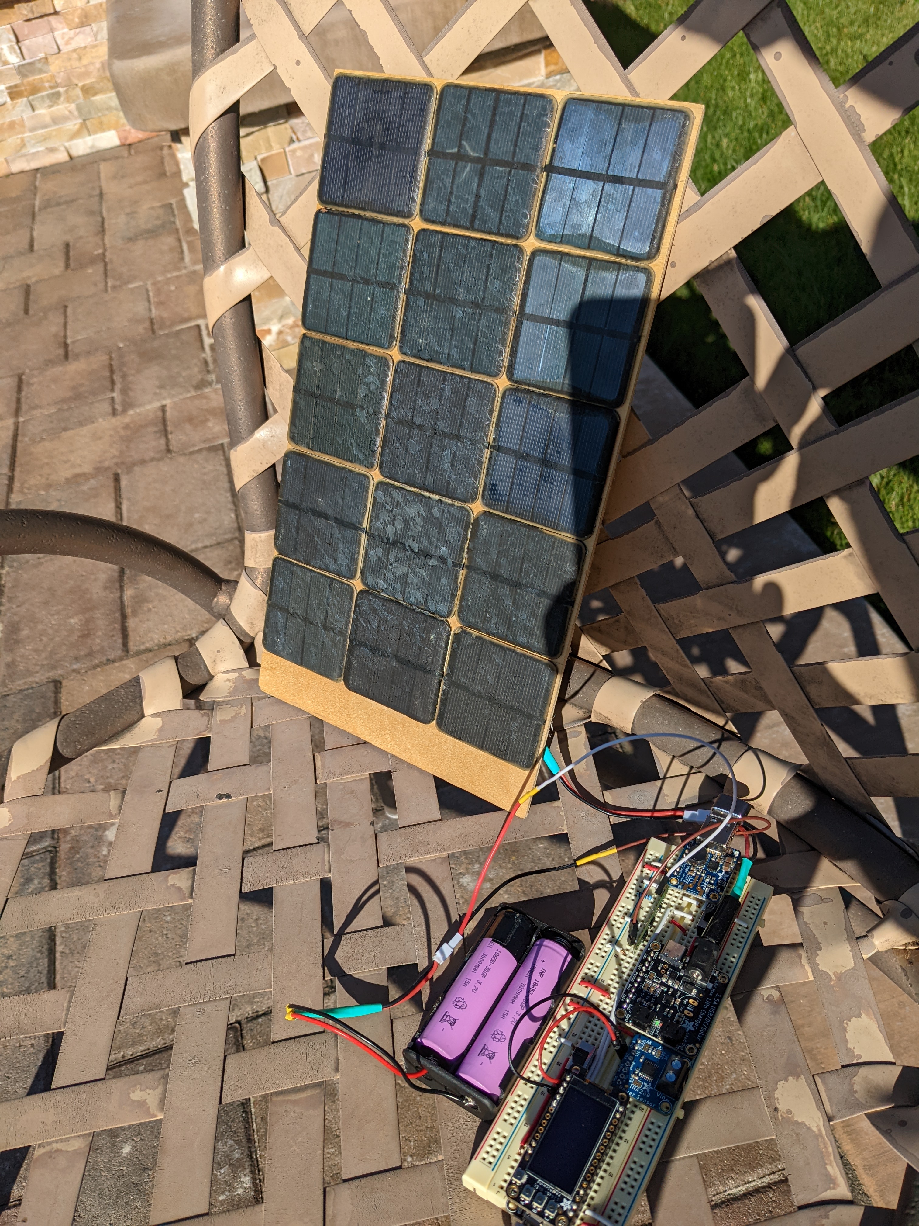
 Panel
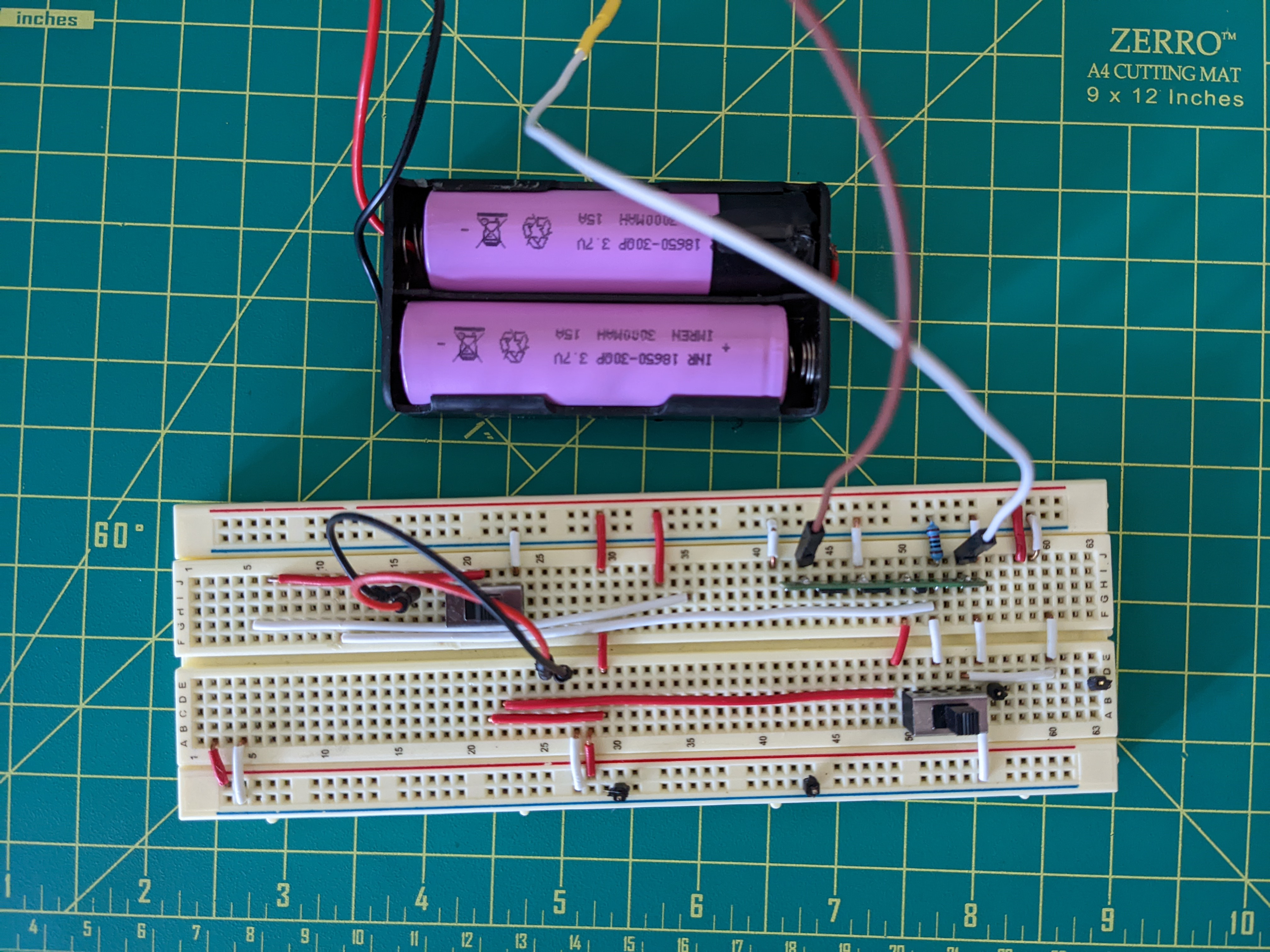
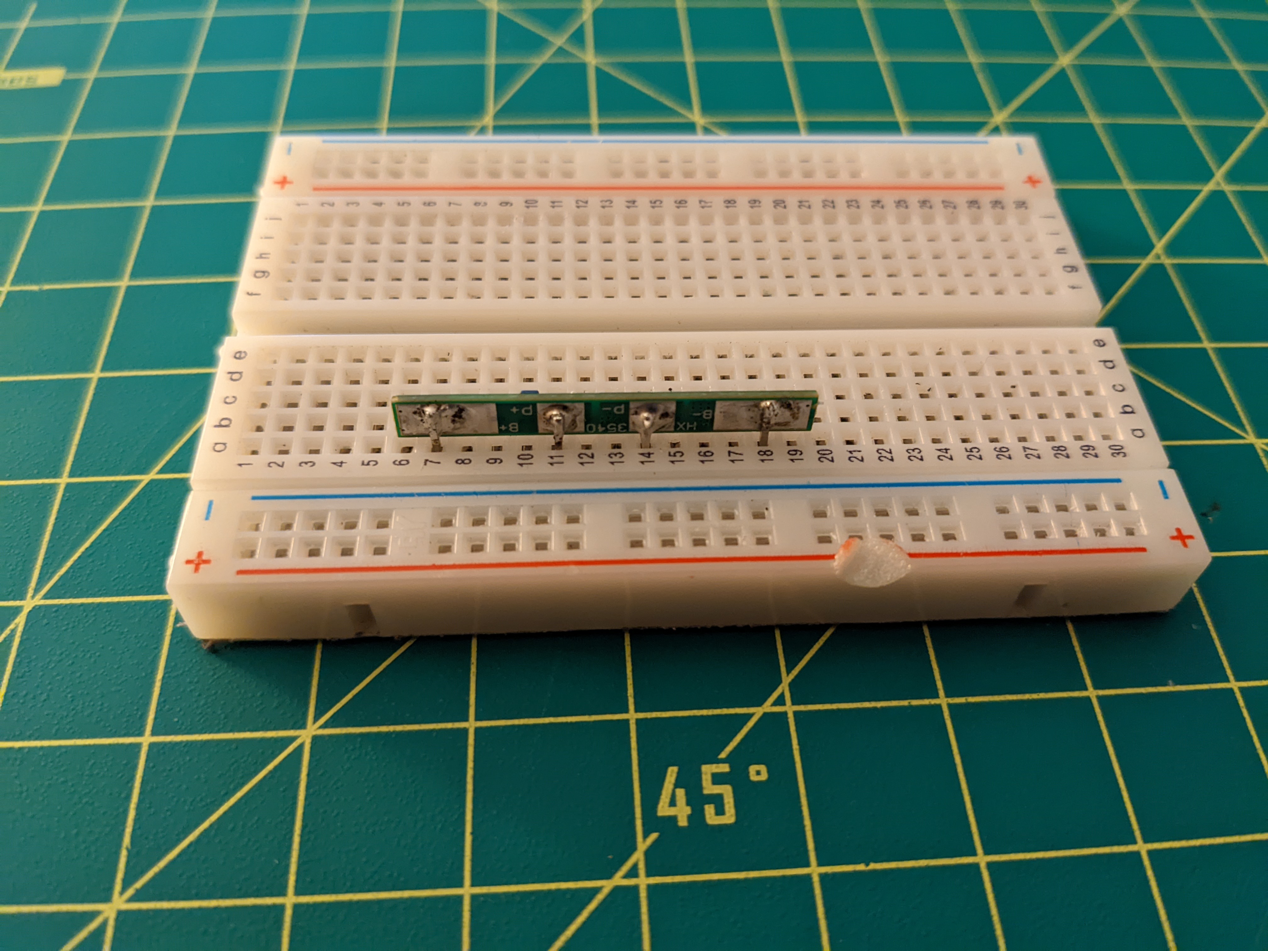
 BMS
BMS
The BMS is really small and can be difficult to mount and use. I thought about hot gluing it to the battery holder and then soldering the wires to it directly. However, I opted against it because I was too afraid that the wires soldered to the P+ and P- and going to the rest of the breadboard would break off easily. Therefore, I soldered pins to the BMS pads and connected it to the system via the breadboard.
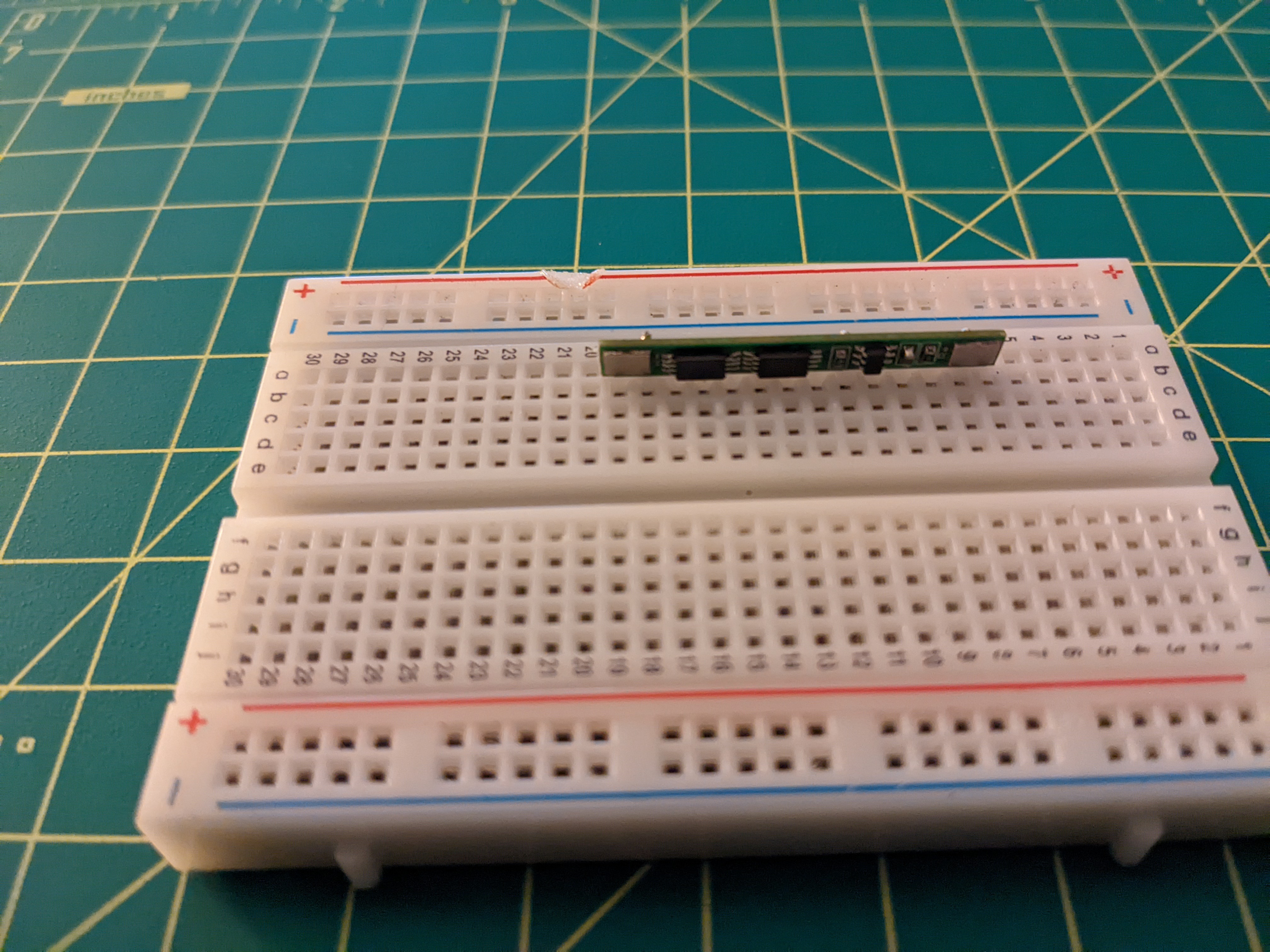
I used the standard header pins that come with a lot of the Arduino type boards and just removed the plastic spacer. I then added pre-tinned the pins as well as the BMS pads. I then inserted the pins into the breadboard at the correct locations then clamped the outer pins to the BMS using a set of helping hands. Then soldered the pins to the pads.
 Battery Holder
The battery holder comes wired in series but this design requires that the batteries be wired in parallel. Connect the positive terminals of both batteries together and add a negative lead wire from the end of the holder that connects the two batteries. Insert one of the batteries in reverse where the spring is touching the positive end of the battery.
Warning
Inserting the batteries incorrectly will cause them to short!
 Services
 Software
- arduino-cli
- ubuntu server
- go-task
- GNU Screen
- jq (for go-task)
- pre-commit
- arduino-lint
- yamllint
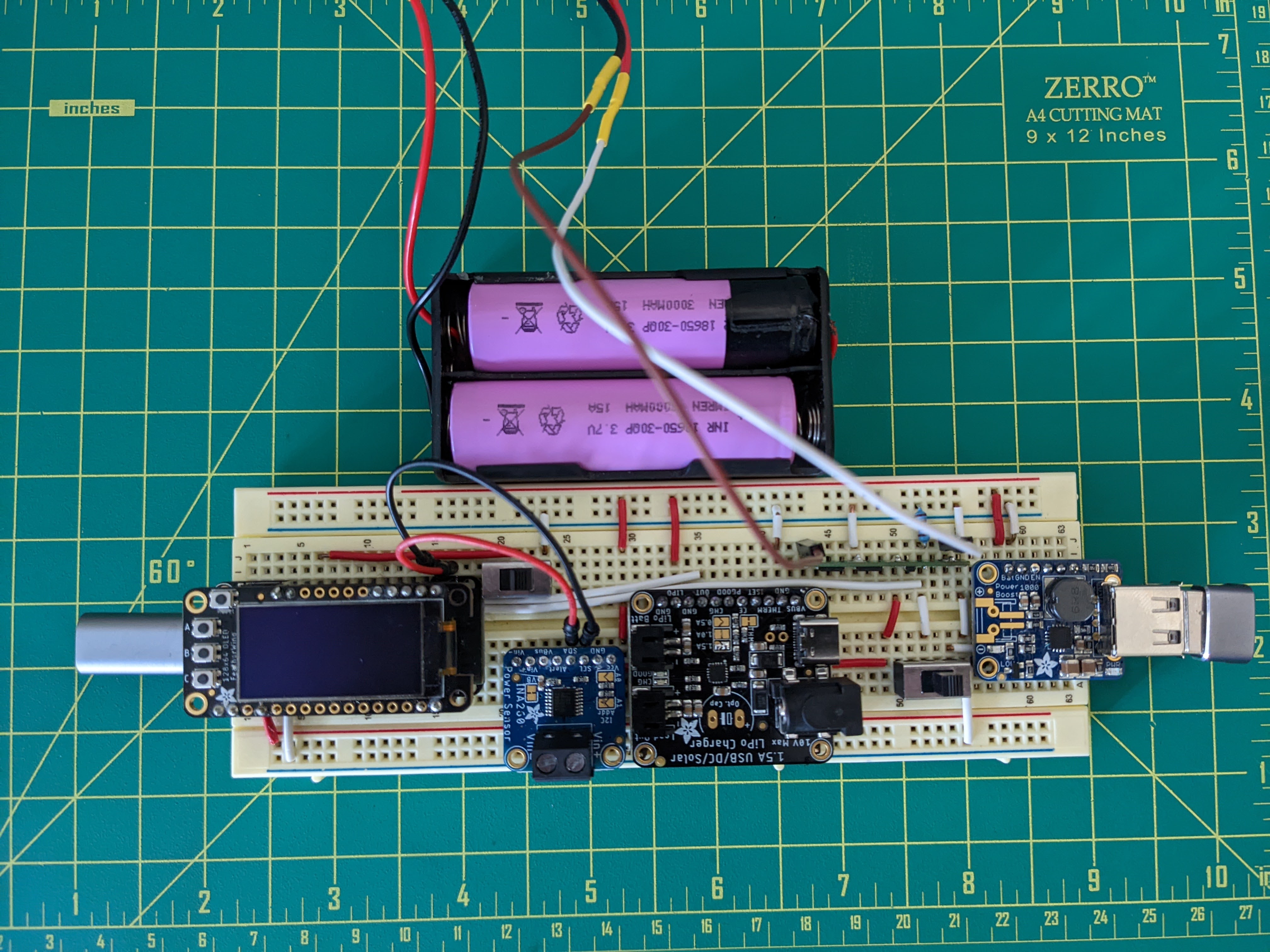
 Circuit
- Connect the output of the battery to the
Vin+of the INA260. - Connect the
Vin-of the INA260 to theLIPOpin of the bq24074. - Connect the
BATpin of the Feather to theOUTpin of the bq24074. - Connect a 1P2T switch to the
ENpin of the Feather to ground. - Connect a 1P2T switch to the
ENpin of the Powerboost and a10kΩresistor. - Connect pin 33 of the Feather to a node between the Powerboost switch and the
10kΩresistor. - Connect all
GNDpins together. - Connect the
SCLandSCApins of the Feather to theSCLandSCApins of the INA260. - Connect the
3Vpin of the Feather to theVCCpin of the INA260. - Connect the BMS in between the battery, ground, and
V+of the INA260.
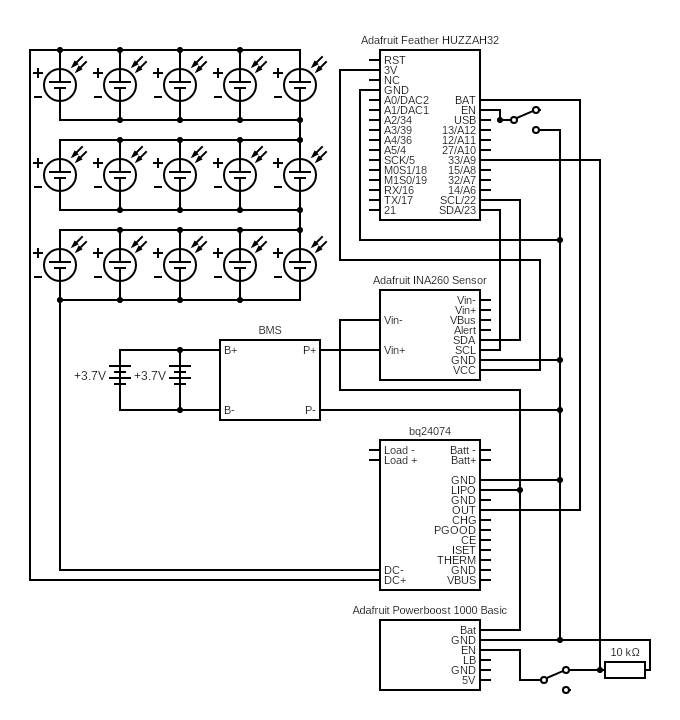
Circuits made with Circuit Diagram
Warning
The li-ion batteries are wired in parallel even though the 2 battery holder come wired in series.
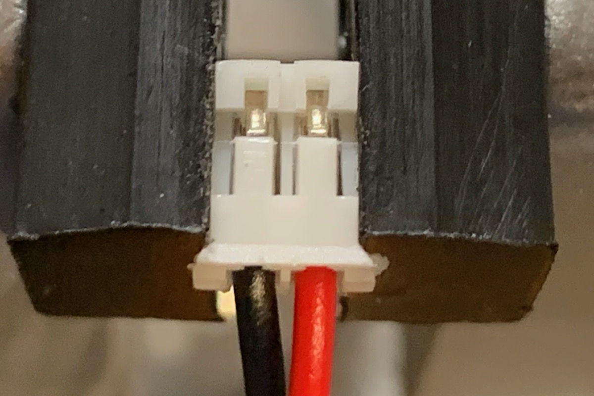
Warning
The JST pins, depending on where they are purchased, may be backwards in terms of the wiring. See this link to determine the correct wiring according to IoT convention.
IoT devices must use batteries wired like this: With the key facing down and the wires toward you, the red is on the right.