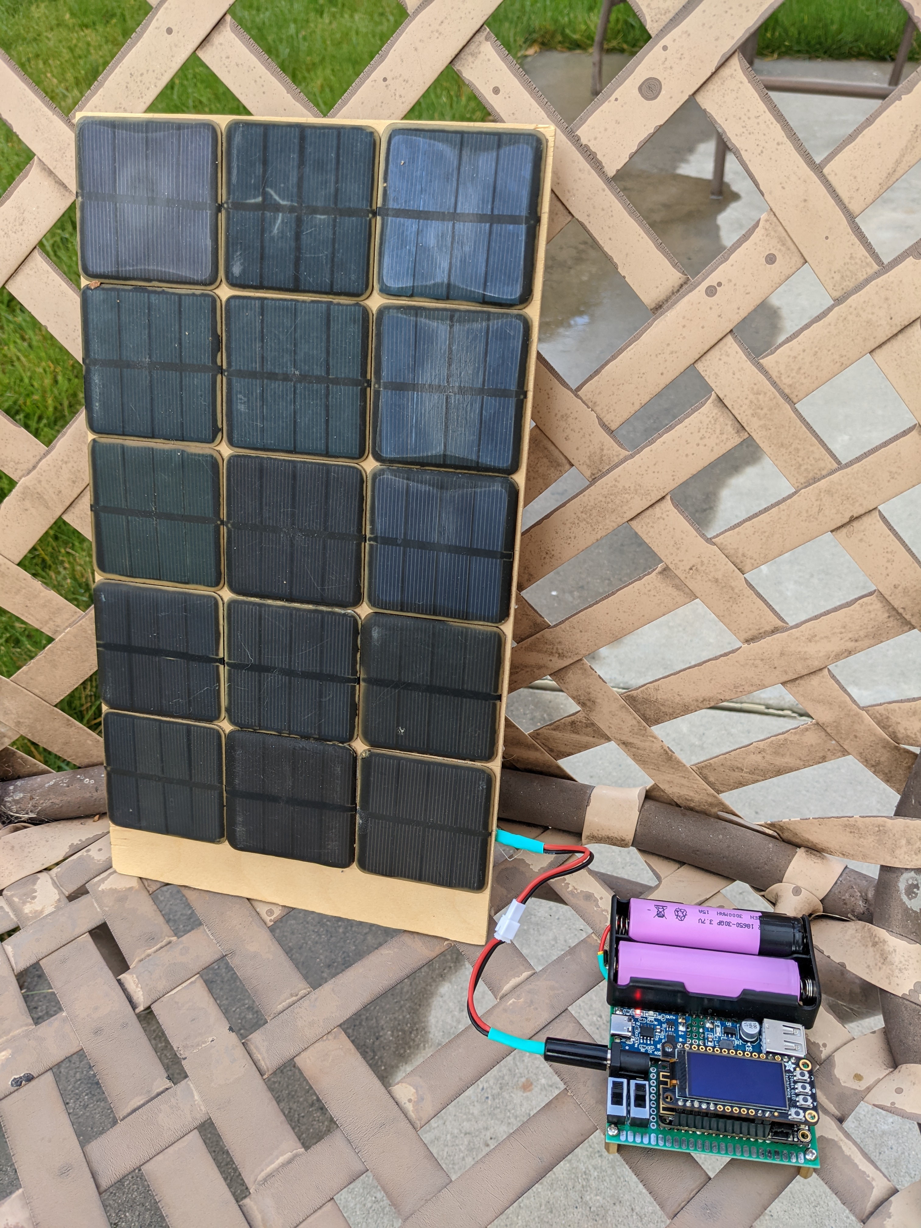
panel
Measure the voltage and current of a solar panel made of multiple solar cells.
Hypothesis
The output of a solar panel is around 7.5V and 500mA made from 15 solar cells with an output of 2.5V and 100mA.
The salvaged solar cells are to wired up in series and parallel to create solare panel that would produce more voltage and current needed for the TP4056.
Assumptions
WIP
Procedure
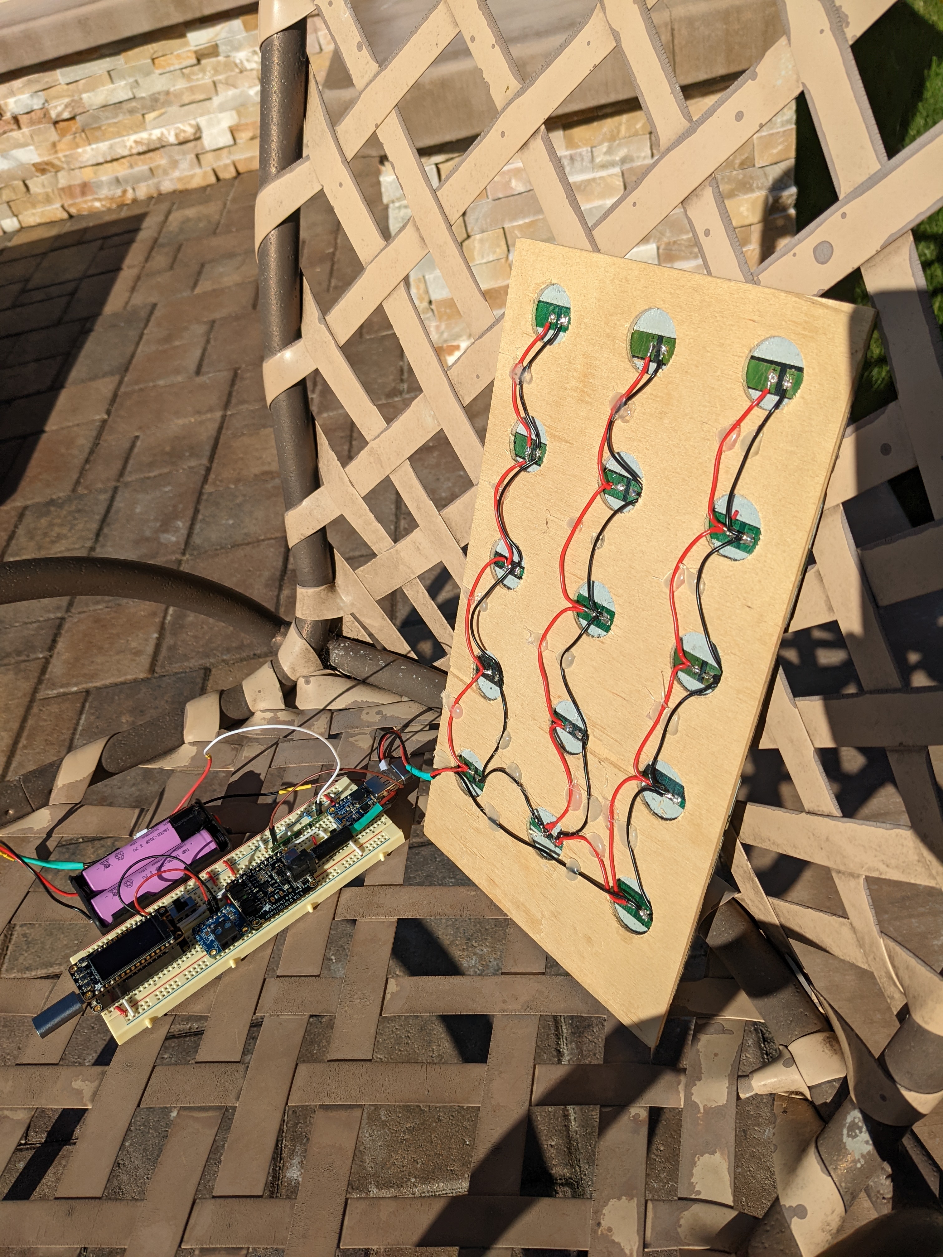
Circuit
There are 3 rows of cells that are wired in series and each row is wired in parallel.
Each row consists of 5 cells wired in paralle with an output of 2.5V at 500mA which makes the panel a total of 7.5V at 500mA for the entire panel.
Connect a 20Ω resistor to the solar panel.
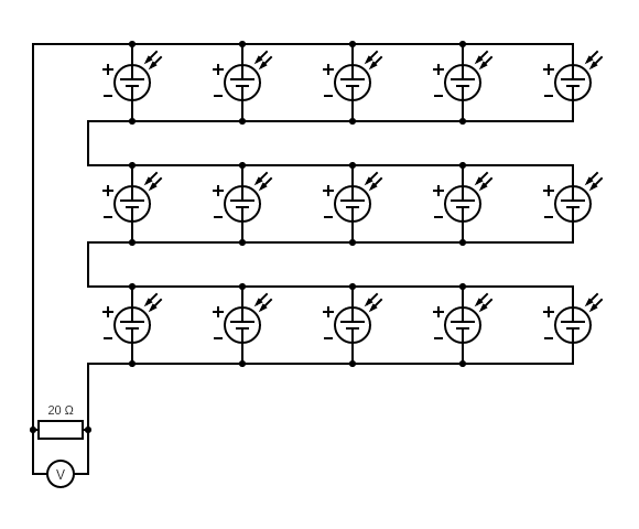
Circuit made with Circuit Diagram
Output
Measure the actual resistance of the resistor.
Measure the voltage across the resistor when the cell is in direct sun light.
Analysis
The current through the resistor can be calculated using Ohm's law.
Using our measure values.
Power
The power through the resistor can be calculated using the following formula.
Using our measure values.
Efficiency
According to this site, the average solar radiation intensity is "1000 W/m2 on a clear day at solar noon in the summer months" at the Woods Hole Oceanographic Institution lattitude which is, 41.5255063.
I know that there are a lot of factors that go into this value but this can be used as a very rough starting point.
Solar cell radiation intensity
Conclusion
The overall efficiency seems really low. Perhaps some reasons are that the epoxy surfaces of the cell are dirty or that the circuit isn't optmized for low voltage.
The design may be able to be changed for 2 rows of 10 cells (I have 5 extra cells) rather than 3 rows of 5 cells to increase the overall current but it'll decrease the working voltage.
Plotting an I-V curve for the panel may be helpful in comparing the two designs.
Troubleshooting
WIP