v2
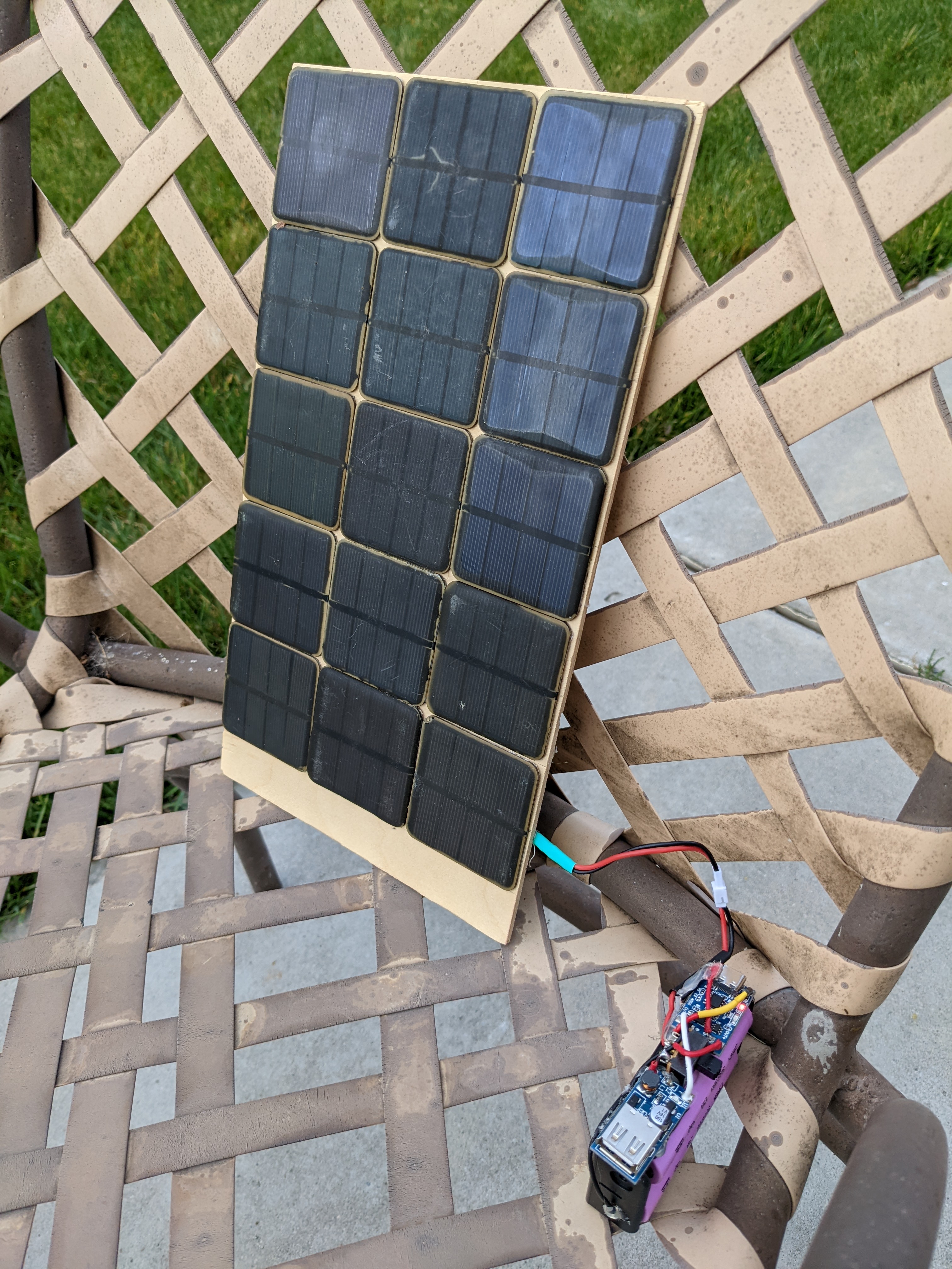
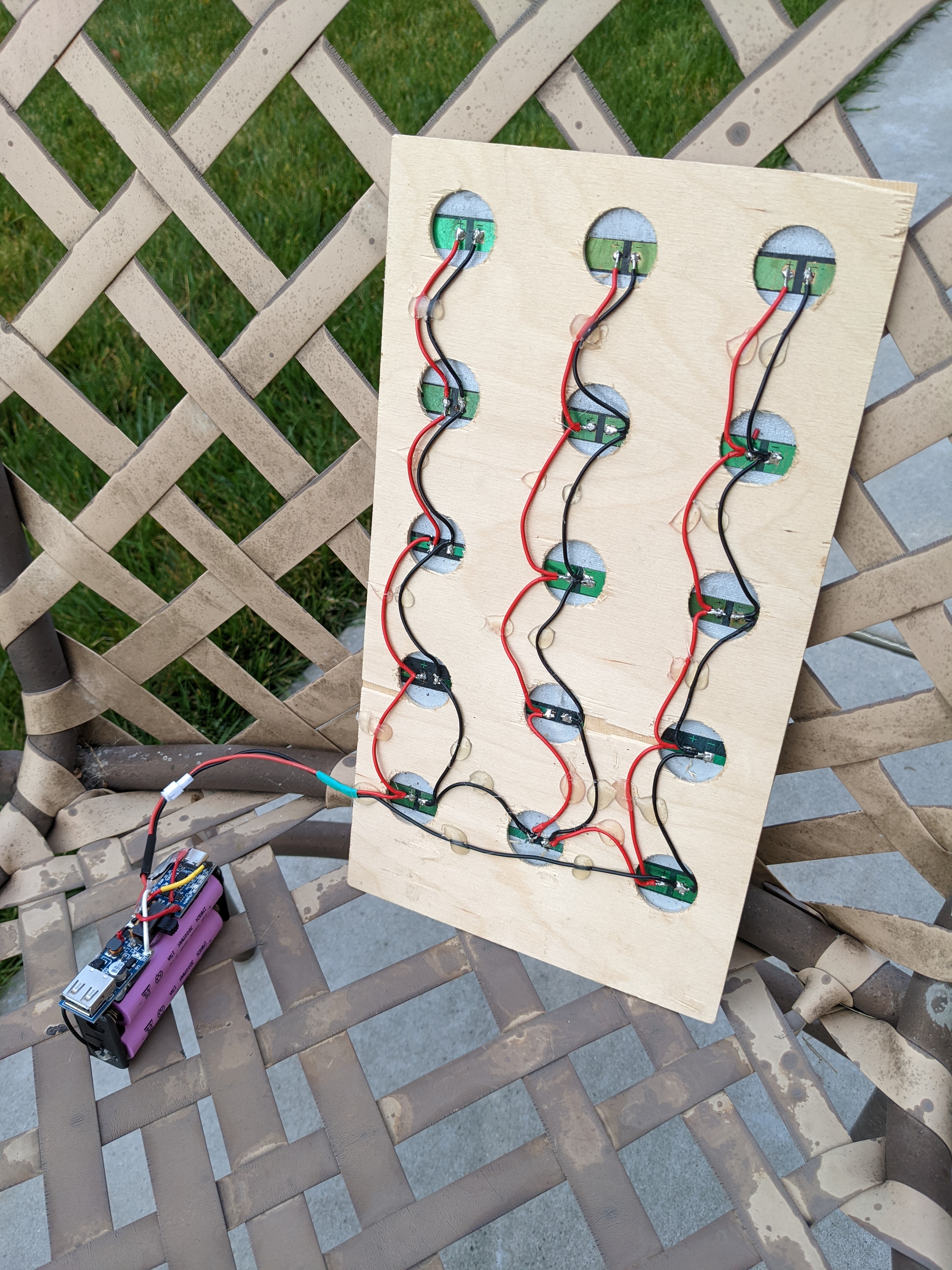
Charge the li-ion batteries using a solar panel and then charge USB devices using the li-ion batteries.
Sketch
The sketch can be found here.
Hypothesis
The TP4056 can be used to charge a 3.7V li-ion battery and then the battery can be used to charge other devices using the USB boost converter.
Assumptions
- One
3.7Vli-ion is being used to capture the soloar energy. - The DPDT switch disallows the li-ion battery from charging and the USB boost converter being used at the same time.
Procedure
Circuit
Connect the solar panel to the IN+ and IN- of the TP4056.
Connect one NC throw of the switch between the solar panel and IN+ of the TP4056.
Connect the other NO throw of the switch between the IN+ of the boost converter and OUT+ of the TP4056.
Connect the 3V li-ion batter to the B+ and B- of the TP4056.
Connect the JST-PH 2.0 connector between the solar panel and the TP4056.
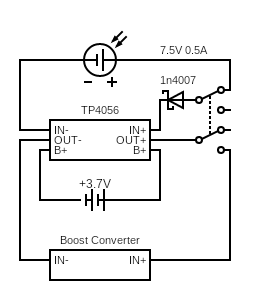
Circuit made with Circuit Diagram
Output
- The red LED on the
TP4056is on when the li-ion battery is charging via the solar panel. - The blue LED on the
TP4056is off when the li-ion battery is charging via the solar panel. - The red LED on the
TP4056is on off the li-ion battery is fully charged and the solar panel is on. - The blue LED on the
TP4056is on when the li-ion battery is fully charged and the solar panel is on. - The red LED on the boost converter is off when the solar panel is on.
- The red LED on the boost converter is on when the solar panel is off.
Analysis
WIP
Conclusion
WIP
Troubleshooting
WIP
References
WIP